-
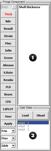
- Figure 1 – FComp Interface
Purpose:
The FComp interface is used to display fringe component data on the model. It allows the selection of various scalar quantities like strains and stresses that can be fringed.
For shells and beams, such data is stored for different integration points through their thicknesses and cross sections respectively. Upon selecting a component to be fringed, further selection of data at a particular integration point can be made using a simple selection widget with options (Low/Mid/Upp/Max/Ave/Min/IPt/BPt).
By default LS-PrePost will fringe the maximum of all integration point data available. Stresses and strains are generally in the global coordinate system (GCS is set by default). This can be changed to Local where the data to be fringed will be made available in element local coordinate system.
User data can be loaded using the User button and fringed. This can be from external third party software or element and nodal results output from the Output Interface on Page 1.
Controls:
- Model selection drop down menu: For use when multiple models are loaded (Md1/Md2/Md3/etc…)
- Fringe Component selection menu

Global Stress/Strain components
Nodal Displacement/Velocity Contour
Stress resultant components
Logarithmic strain components
Pressure, Temperature, Thickness, etc.
Infinitesimal Strains
Green-St. Venant Strains
Almansi Strain
Strain rates
Residual elastic strains
FLD strain components
Beam fringe components
Navier-Stokes components
New database fringe components
User defined fringe components
Collect fringe data
- Fringe: Choose fringe method (Frin/Isos/Lcon/Fiso/XFrn/FMes)
- Integration: Select desired integration point (Low/Mid/Upp/Max/Ave/Min/IPt/BPt)
- Integration Point selection menu

- CS: Choose Global or Local Coordinate System (Element’s Local CS)
