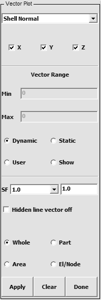
- Figure 1 – Vector Interface
Purpose:
This interface is used to display normal vectors for any element in the model.
Controls:
- Select Vector Type: Choose from list
- (Shell Normal / Displacement / Velocity / Prin. Stress / Prin Strain / P. Inplane Strain / Heat Flux)
 X – Toggle X component of vector
 Y – Toggle Y component of vector
- Z – Toggle Z component of vector
- Vector Range: Enter minimum and maximum values for vector range
- (Press enter to accept values)
 Dynamic – A set of min/max ranges is computed for each time state
 Static – A constant min/max range is computed using all time states
- User – Range set by user, enter min/max values above
- Show – Shows elements within the range entered above
- SF: Enter scale factor for vector plot
- Hidden line vector off – Switch off hidden line for vectors
- (If a vector is behind part of the model it will not be shown, check this option to display the vector)
- Whole – Apply vector plot to whole model
- Part – Pick parts for vector plot
- Area – Define an area for vector plot
- El/Node – Pick an element or node for vector plot
Apply vector plot
Clear vector plot
Exit Vector Plot interface
