-

- Figure 1 – SWGen Interface
Purpose:
Use this interface to generate spotweld elements from a spotweld file.
Interface Description
The primary interface for SWGen is shown in Figure 1. It can generate both solid and beam type 9 spotweld elements, and in doing so automatically creates the following keywords: *PART, *SECTION, *SET_NODE, *SET_PART, *MAT_SPOTWELD, *HOURGLASS, and *CONTACT_SPOTWELD.
Weld Information
Welds can be generated by reading information from an external Weld File. 3 predefined formats (Primer, MWF, and XML) as well as a Custom option are supported. Each of these is discussed below in more detail.
The only mandatory attribute for each weld is its coordinate. Other optional attributes are weld ID and part IDs specifying connectivity. The weld ID is used only for identifying welds that for some reason fail to be created (LS-PrePost will report a list of such IDs). If part IDs are provided, LS-PrePost will only allow connections to those specified (maximum number of parts per weld = 5).
If part IDs are given for a weld, only those parts will be connected in LS-PrePost when the welds are being created. Multiple parts will be connected from one weld coordinate if they are within Search radius of the coordinate and if the user has chosen to allow connections to those parts. The Unload WF button will remove all weld info (weld file data) in the model but not any finite elements.
Weld File Formats
Note that all part IDs are interpreted as LS-DYNA Part IDs for the weld file formats: Primer, MWF, and XML. Using the Custom file reader, LS-DYNA PartID or PART HEADING can be used for part identification.
- XML – not “real” XML because syntax is not case sensitive and newline characters must exist as shown
- <?xml version=”1.0″?>
- <Welds>
- <Weld id=”100202″>
- <X>10.2</X>
- <Y>232.2</Y>
- <Z>23</Z>
- <PID1>200</PID1>
- <PID2>300</PID2>
- </Weld>
- <Weld id=”100203″>
- <X>20.2</X>
- <Y>232.2</Y>
- <Z>23</Z>
- <PID1>200</PID1>
- <PID2>400</PID2>
- <PID3>500</PID3>
- </Weld>
- </Welds>
- MWF (Master Weld File) – free file format with “::” (double colon) as separators
- # WELD_ID::NUM_PIDS::X::Y::Z::PID_1::PID_2::PID_3::PID_4::PID_5::GRP_ID
- 1::2::2875.8::-583.666::1452.53::15257365::15257369::”CG1″
- 1::2::4027.738118::-745.446933::379.446477::15261680::15251246::”CG795″
- Primer – fixed file format, commented lines starting with “$”
- $ 10 20 30 40 50 60 70 80 90 100
- $ < weld ID> < X coord>< Y coord>< Z coord> < Part 1 >< Part 2 >< Part 3 >< Part 4 >
- SPOTWELD 1 POINT 2173.4331-644.90894 283.17007 PARTS 64000 42000
- SPOTWELD 2 POINT 2197.3462-640.45935 337.95139 PARTS 64000 42000
- Custom
The custom reader can interpret both csv (comma separated value) files and fixed format files. The user must pick between the two by activating the appropriate radio button on the left.
-

- Figure 2 – SWGen Custom Example
If csv is chosen as in the above image, field “2” of each line in the file is interpreted as Weld ID. Field “4” is interpreted as X coordinate, and so on. (Note that the first field in a comma separated file is index “1”)
If fixed is chosen, the character column interval for each item is written in the text field. (Note that the first column in a file is number “1”) Only X, Y, and Z are mandatory fields, and all others can be set to “0”. If Part HEADING is toggled, the ID field will be matched against the LS-DYNA part HEADING (on *PART) instead of the LS-DYNA *PART ID. Note that blank space between characters will be ignored and the heading is case sensitive. For example, the heading “left fender ” in a keyword file will match the text string “leftfender” in a weld file, but “Left Fender” will not be a match.
Skip lines will ignore a user-defined number of lines at the beginning of the file. Read lines will read the specified number of lines after “Skip lines”. If “Read Lines” is set to zero, LS-PrePost will read all lines until the end of the file.
How Weld Generation Works

- Figure 3 – Layer Welding
Spotwelds are physical connections between two (or multiple) layers of parallel sheets of metal. As stated above, the only thing needed for creating a spotweld connection is its coordinate. The weld coordinate does not have to be on a FE node position, but the layers of parts to be connected should be reasonable parallel.
The weld connection points (nodes for the weld elements) will be created on the weld normal direction defined by: weld_coordinate_from_file + t*closest_element_normal. Only one connection point will be created for each part and weld info. This means that the elements being connected for one weld point have to belong to separate parts, like in the figure to the right.
Evaluating Weld Information
- Figure 4 – Create

- Figure 5 – Accept
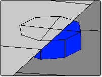
After the weld data is read in from file, the information is evaluated to see if it is possible to create weld elements based on the given data and search radius. If parts are specified in the weld information, LS-PrePost will only try to connect those parts. If no part IDs are given in the weld file, LS-PrePost will try to connect all parts within a distance specified by “Search radius”. If weld elements cannot be created from the weld information, it will be reported in the message window. A file called “failed.spot” will also be written with a list of failed welds and reason for failure (if available). In addition, the weld markers for those that failed will turn red.
If weld elements are calculated to be shorter than the value specified in Min Length, they will also be reported to the message window and the weld markers will turn yellow. For welds that can be successfully created, the weld markers will turn blue. When Create is clicked, a line is graphically displayed where beam weld elements will be created, and solid blocks are displayed where solid elements will be created (see Figure 4).
When Accept is clicked, nodes on the preview solid elements are projected in the weld normal direction to the element face they will be tied to. If the projection of any node falls outside the face to tie to, the node on the solid weld element is moved to the closest point on the part to connect from its preview position (see Figure 5). These nodes are moved 0.1% inside the element face to ensure they will be tied by LS-DYNA. All nodes that are moved laterally like this are stored in a node set called “Laterally moved spotweld nodes” so they easily can be reviewed later in a manual ocular inspection.
Spotweld Properties
Two different methods for defining spotweld properties exist: GUI or File.
- GUI
As mentioned above, Beam or Solid elements can be chosen for the weld elements. The Weld diameter value can be set in the interface as shown in Figure 1. If solid type elements are chosen, the area of the solid elements will be the same as if the weld was circular.
The diameter for the welds can be set to Constant by selected the first radio button in the list. If Curve ID is selected, the *DEFINE_CURVE keyword can be used to describe weld diameter as a function of minimum thickness of the two parts being connected (note that solid elements have zero thickness). If Built-in is selected, the empiric formula: 5*(min_thickness_of_connected_parts)^0.5 is used.
New parts for the weld elements are created with a description in the part headings of which parts are being connected. For example: “sw_21_115” means parts 21 and 115 are connected by this spotweld part.
Beam section cards with element type 9 and the specified diameter are created. A section card is created for solid elements too, but here the diameter is determined by the size of the elements themselves. Type 1 solid elements are created with the recommended hourglass control applied.
A *MAT_SPOTWELD keyword is automatically created for each combination of parts being connected. This is to make it easier to introduce modifications later if the same material parameters are not desired for all weld connections. The default material parameters can be changed by clicking Mat. Properties button as shown below.
-

- Figure 6 – *MAT_SPOTWELD
- File
This option provides much more refined control of the properties on the spotwelds to be generated. The property inputs (weld diameter, failure parameters, NRR, NRS, NRT, SIGY, SECTION_BEAM parameters, and hexa element type) are all defined in a text file. An example spotweld configuration file: spotweld.conf
A spotweld configuration file can be read in by using the Browse button or typing in the file name and hitting Enter in the text field. Currently active spotweld property file settings can be viewed by clicking the View button.
Treatment of *CONTACT_SPOTWELD
It is recommended that only one *CONTACT_SPOTWELD keyword is used in a LS-DYNA model. If *CONTACT_SPOTWELD exists with either a *PART or *SET_PART defined as master, the contact keyword is modified to include the new weld elements. Also, nodes tied to deformable master elements will be included in the slave node set for *CONTACT_SPOTWELD. However, if the weld nodes are tied to an element with any of its nodes included in a *CONSTRAINED_NODAL_RIGID_BODY, the weld node will be added to the nodal rigid body and not to the spotweld slave node set. Further, if the weld node is tied to an element with a *MAT_RIGID material, the node is added as an *CONSTRAINED_EXTRA_NODE to that part and not to the slave node set. If no *CONTACT_SPOTWELD exist, one is automatically created.
