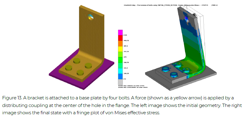
Eigenfrequency analyses of the bolted assembly of Section 4.2.2 at t = 0 (initial configuration without bolt pre-tension), t = 1 (bolt pre-tension applied) and t = 2 (bolt pre-tension and loading is applied). The example keyword file is eigen002.key.
Example Files: eigen002
NOTE! All examples are included in the Complete Guideline
At t = 0, six rigid body modes are found, indicating that the assembly, at this stage, is not connected. After bolt pre-tensioning, at t = 1, the lowest eigenfrequency is 479 Hz. At t = 2, when also the loading is applied, the lowest eigenfrequency decreases to 104 Hz.
*KEYWORD
$===============================================================================
$ Geometry
$===============================================================================
*INCLUDE
bolts_geo.key
$===============================================================================
$ Control and output cards
$===============================================================================
*INCLUDE
../INCLUDE_FILES/control_cards_nonlin.key
*INCLUDE
../INCLUDE_FILES/database_cards_static.key
*CONTROL_TERMINATION
$   ENDTIM    ENDCYC     DTMIN    ENDENG    ENDMAS
        4.
*CONTROL_IMPLICIT_DYNAMICS
$    IMASS     GAMMA      BETA                                   IRATE
         1       0.6      0.38       0.0       0.5      0.70         1
*DEFINE_CURVE_TITLE
Time stepping curve
       700
                  0.                0.05
                  1.                 0.2
                  2.                 0.2
                  3.                 0.2
                  4.                 0.2
                  5.                 0.2
*DEFINE_CURVE_TITLE
Eigenvalue analyses
701,
0.,10
1.,10
2.,10
3.,10
*CONTROL_IMPLICIT_EIGENVALUE
      -701
                                                 1
*CONTROL_MPP_IO_NODUMP
$===============================================================================
$ Contacts
$===============================================================================
*CONTACT_AUTOMATIC_SINGLE_SURFACE_MORTAR_ID
1010      Bolts all contact
       111                   2
      0.15
        5.


         5
$===============================================================================
$ Loading and boundary conditions
$===============================================================================
*BOUNDARY_SPC_SET
       112                   1         1         1
$ --- Bolts pre-tensioning
*INITIAL_STRESS_SECTION
         1         1      1002         4
         2         2      1002         4
         3         3      1002         4
         4         4      1002         4
*DEFINE_CURVE_TITLE
Bolt pre-tension 448 MPa
      1002                          448.
0.,0.
1.,1.
$ --- Loading
*LOAD_NODE_SET
$     nsid       dof      lcid        sf
       109         1      1001      1.E3
       109         2      2001      1.E3
*DEFINE_CURVE_TITLE
Loading X
      1001
0.,0.
1.,0.
2.,1.
3.,0.
*DEFINE_CURVE_TITLE
Loading Y
      2001
0.,0.
1.,0.
2.,0.
3.,1.
4.,0.
$===============================================================================
$ Additional output - elout
$===============================================================================
*DATABASE_HISTORY_NODE_SET
       109
*CONTACT_FORCE_TRANSDUCER_PENALTY_ID
  19000004Bolts to plate
         4       101         2         3


$===============================================================================
$ Simulation title
$===============================================================================
*TITLE
Bolts pre-tensioning example
*END