Purpose:
The main purpose of this interface is to provide various mesh quality check and repair functions in one central area. Single element creation for various element types is available, and splitting of shells using various schemes is available for quick repair of an existing mesh.
Under the node editing section, new nodes can be created in various ways, and there are several methods of replacing, aligning, and modifying nodal locations to assist in mesh clean-up.
Node Controls:
-

- Figure 1 – ElEdit / Node / Show
 Show – Show nodes interface (see Figure 1)
 Show Free Edges – Find and show free edges
Toggle display of unreferenced nodes on/off
Exit this interface
-

- Figure 2 – ElEdit / Node / Delete
 Delete – Delete nodes interface (see Figure 2)
- Show Free Edges – Find and show free edges
 Del_Beam3rdNode – Delete beam third nodes
Delete selected nodes
Cancel last deletion
Commit deleted node
Turn on or off all reference nodes
Exit this interface
-

- Figure 3 – ElEdit / Node / Create
- Create – Create nodes interface (see Figure 3)
- Show Free Edges – Find and show free edges
- ByOne – Create one node
- Node – Pick node on model to define new node coordinate
- Position – Pick a position to define new node coordinate
Call Position Dialog
- X/Y/Z: Enter X/Y/Z coordinate of a new node
- Node Id: Input node ID
Get new default ID
Create nodes
Reject last created nodes
Commit created nodes and clear all of them from screen
-

- Figure 3b – ElEdit / Node / Create / ByOne
- ByTwo – Create nodes between two nodes
- Node – Pick node on model to define new node coordinate
- Position – Pick a position to define new node coordinate
- EndIn – Create new nodes at N1 and N2 also
- N1 – Pick node or ender node ID to define first point
- N2 – Pick node or ender node ID to define second point
- Num: Set create node number
- Head X/Y/Z: Head X/Y/Z coordinate
- Tail X/Y/Z: Tail X/Y/Z coordinate
-

- Figure 3c – ElEdit / Node / Create / ByTwo
- OnCurve – Create nodes on a curve
- Point – Pick point on a line
- ByNum – Create any number of evenly spaced nodes on a line
- XYZ: Enter XYZ coordinate of new node
- Num: Set number of nodes to create
-

- Figure 3d – ElEdit / Node / Create / OnCurve
-
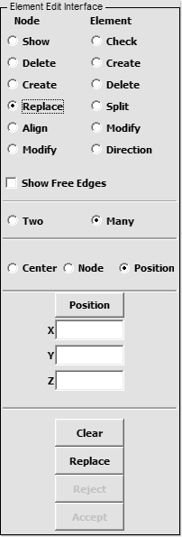
- Figure 4 – ElEdit / Node / Replace
- Replace – Replace or merge nodes interface (see Figure 4)
- Show Free Edges – Find and show free edges
- Two – Replace node by two
- Pick Node – Pick Node
- Area – By area select nodes
- Node 1 – Pick node on model
- Node 2 – Pick node on model
- At Node1 – Move Node2 to Node1
- At Node2 – Move Node1 to Node2
- Midpoint – Move Node1 and Node2 to Midpoint
Clear node 1 and 2
Reject last replacement node
Accept replacement node
-

- Figure 4b – ElEdit / Node / Replace Two
- Many – Replace many nodes
- Center – Take center for replace target position
- Node – Pick node for replace target node
- pickNode – Pick node for replace target position
- Node: Node id for replace target node
- Position – Call position dialog and get target position
Call Position Dialog
- X/Y/Z: Enter X/Y/Z coordinate of new point 2
Clear target and picked nodes
Replace nodes by target position
Reject last replacement node
Accept replacement node
-

- Figure 5 – ElEdit / Node / Align
- Align – Align nodes interface (see figure 5)
- Show Free Edges – Find and show free edges
- Node – Define points by node and pick odes to align
- PtOnElm – Define points on elements and pick nodes to align
- Point 1 – Pick or define point 1
- Point 2 – Pick or define point 2
- X/Y/Z – Enter X/Y/Z coordinate of new point 1/2
Clear position 1 and 2, and picked nodes
Align nodes on line between points 1 and 2
Reject last aligned node
Accept alignment
Exit this interface
-

- Figure 6 – ElEdit / Node / Modify
- Modify – Modify nodes interface (see Figure 6)
- Show Free Edges – Find and show free edges
- In Plane – In plane
- Pick Node – Pick node to modify
Popup dialog get position
- X/Y/Z: Enter X/Y/Z coordinate of new position
- Quality Check – Check element quality when modifying node
- Out Plane – Out plane
- Pick Node – Pick node to modify
- Distance: Input distance
- X/Y/Z: Enter X/Y/Z coordinate of new position
- +/-: Increment/Decrement by distance value
- Quality Check – Check element quality when modifying node
Reject last modify node
Accept modified nodes
Exit this interface
Element Controls:
-

- Figure 7 – ElEdit / Element / Check
- Check – Check elements interface (see Figure 7)
- Show Free Edges – Find and show free edges
- Choose element type to check:
- Beam
- Shell
- Solid
- Tshell
- Checking Method: Select entity type to be checked from list
- Criterion: Enter check criterion value
Press to perform checking
Exit element check interface
Change ordering node sequence in a solid (button appears in bottom panel)
-

- Figure 8 – ElEdit / Element / Create
- Create – Create elements interface (see Figure 8)
- Show Free Edges – Find and show free edges
- Choose element type to create:
- Beam
- Tria
- Quad
- Tetra
- Penta
- Hexa
- Discrete
- Element ID: Input Element ID
- Part ID: Input part ID
- Pick PID – Pick part ID
Get new default element ID
Get new default part ID
Clear all fields and set default new node ID
Create nodes and put into temporary buffer
Reject last created nodes
Commit created nodes and clear them from screen
- Pick node on model or enter node number:
- Node1 (all element types)
- Node2 (all element types)
- Node3 (all element types but Discrete)
- Node4 (Quad, Tetra, Penta, and Hexa)
- Node5 (Penta and Hexa)
- Node6 (Penta and Hexa)
- Node7 (Hexa only)
- Node8 (Hexa only)
- QuickBeam – Create beams with just 2 nodes (Beam only)
- VID: Orientation option (Discrete only)
- S: Scale factor on forces (Discrete only)
-

- Figure 8b – ElEdit / Element / Create Quad
-

- Figure 9 – ElEdit / Element / Delete
- Delete – Delete elements interface
- Show Free Edges – Find and show free edges
- Choose element type to delete:
- Any
- Beam
- Shell (Any/Tria/Quad)
- Solid (Any/Hexa/Panta/Tetra)
- Tshell (Any/Tria/Quad)
- Discrete
- Sph
- Inertia
- Seatbelt
- Remove Unref Node – Remove unreferenced nodes
Delete elements
Reject deletion (reset)
Make deletion permanent
-

- Figure 10 – ElEdit / Element / Split
- Split – Split shell elements interface (see Figure 10)
- Show Free Edges – Find and show free edges
- Click the icon that represents the appropriate type of splitting operation.
- The check boxes allow quads and trias to be selected simultaneously
- Perp Edge – Split elements in the direction perpendicular to edge
- // Edge – Split elements in the direction parallel to edge
- One – Split one by one according to pick point
- F_P – Split elements from element first point
- S_P – Split elements from element second point
Apply split element
Reject last split element
Accept all split elements
-

- Figure 11 – ElEdit / Element / Modify
- Modify – Modify elements interface (see Figure 11)
- Show Free Edges – Find and show free edges
- TwoTria – Change two triangles
- TriaQuad – Split TriaQuad to five triangles
- Quality Check – Check element quality when modifying element
-

- Figure 12 – ElEdit / Element / Direction
- Direction – Element orientation (default material direction) interface (see Figure 12)
The default material direction, also known as the material reference system, can be viewed, set, and/or modified for both shell and solid elements using this interface. This material orientation is used directly when AOPT=0 for anisotropic materials or may be used as a reference orientation for other values of AOPT (see LS-DYNA keyword manual for further details). The default material system is set with the PSI parameter on *ELEMENT_SHELL and the A and D vectors that can be set on *ELEMENT_SHELL_ORTHO. The *ELEMENT cards will automatically get the options _BETA or _ORTHO if they initially don’t have these options.
- Shell
The A-axis for the element is shown with a red arrow. The PSI value on *ELEMENT_SHELL_BETA can be changed using three different methods:
- 1. Vector – Projects the given vector onto the selected shells in each shell normal direction and sets the PSI angle to match this projected vector.
- 2. Rotate – Rotates the material direction by increasing or decreasing the PSI angle. Rot+ means that the material direction is rotated in the positive direction about the shell element normal.
- 3. Set PSI – Sets the PSI angle for the selected shell elements with the given value. If the value zero (0.) is used for PSI, the element type will be changed from _BETA, _THICKNESS_BETA, or _THICKNESS to just *ELEMENT (without options) provided the values for node thickness are all zeros.
- Solid
The A-axis for the element is shown with a red arrow, and the B-axis is shown with a shorter green arrow unless the D vector has zero length since the meaning of the A and D vectors no longer represent the default material system (see LS-DYNA keyword manual). The reference material axis can be set using two methods:
- 1. Vector – The A and D vectors are explicitly set and applied.
- 2. Rotate – The default material system can be rotated about a global vector with the Global direction option, or it can be rotated about local A, B, or C axis in the current element default material system with the Local ele. Axis.
