The basic recommendation for sliding contacts in implicit analyses is to always use the Mortar contacts:
The Mortar contacts use a segment-to-segment formulation, which is based on consistent FE theory
(contact stress consistent with element shape functions). It has smooth force transitions for penetration
and segment to segment sliding. The Mortar contact aims at capturing most contact situations that may
occur in a typical LS-DYNA model.
New contact segments revealed due to element erosion are also accounted for. With the single surface Mortar
contact, it is possible to include the whole model in one contact definition also for implicit analyses, and let LS-DYNA automatically find
the potential contact situations.
The Mortar contacts normally require a minimum of input. As a starting point, just define what should be in contact
using parts or part sets, and specify the coefficient of friction. It is recommended to use the softer part
(less stiff material, or coarsest mesh) as tracked. A basic keyword example follows, to define contact between
Part Set ID 10001 and part 50000001 with a coefficient of friction of 0.2:
*CONTACT_AUTOMATIC_SURFACE_TO_SURFACE_MORTAR_ID
$#     cid
10000004  PLATEN to BiW
$#   surfa     surfb  surfatyp  surfbtyp   saboxid   sbboxid      sapr      sbpr
     10001  50000001         2         3
$#      fs        fd        dc        vc       vdc    penchk        bt        dt
       0.2
$#     sfs       sfm       sst       mst      sfst      sfmt       fsf       vsf
The Mortar contacts also support more advanced options,like pressure dependent friction and thermal options.
The Mortar contacts use a penalty formulation. This means that forces are applied in order to prevent the
different parts in contact from occupying the same location. The force is related to the penetration depth,
implying that a small penetration is required to develop a contact force. The Mortar contact prints the
maximum penetration in the mes* – file(s), and also in the sleout file for time history plotting and the
d3plot files for fringeploting.
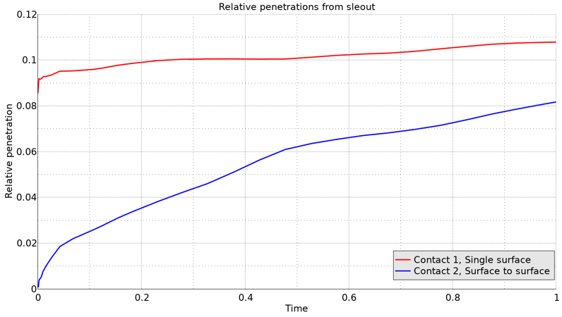
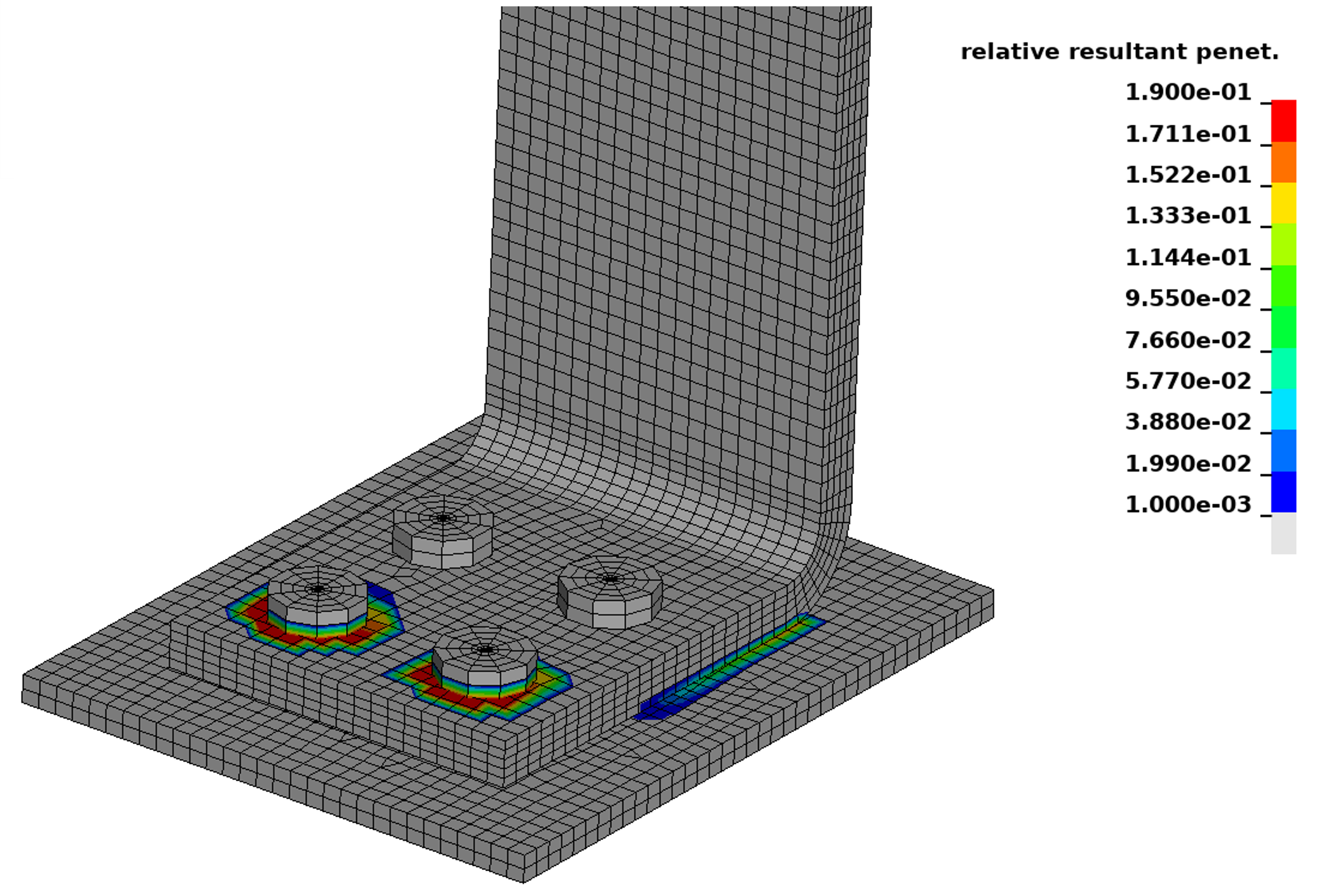
The left image shows an example of the maximum penetration history from sleout. The right image shows a fringe plot of the
relative resultant penetration.
Mortar contacts are also available for 2D analyses,
The basic recommendation is avoid unintended initial penetrations. Use your preprocessor (for example LS-PrePost) to check and fix
unintended initial penetrations in the model. In practice, a completely penetration free model is very hard to achieve, and the Mortar
contacts can handle initial penetrations within “reasonable” limits. The default behavior is that the contact surface is adjusted during
the initialization, so that the initial position of the parts is assumed to correspond to zero contact pressure.
The Mortar contacts can also handle situations with intended initial penetrations, corresponding to “press fit” or “grip” between
parts. This is activated by the IGNORE variable, see the keyword example:
*CONTACT_AUTOMATIC_SURFACE_TO_SURFACE_MORTAR_ID
$#     cid                                                                 title
1010      Pressfit example
$#   surfa     surfb  surfatyp  surfbtyp   saboxid   sbboxid      sapr      sbpr
         5         4         3         3
$#      fs        fd        dc        vc       vdc    penchk        bt        dt
      0.10
$#    sfsa      sfsb      sast      sbst     sfsat     sfsbt       fsf       vsf

$#    soft    sofscl    lcidab    maxpar     sbopt     depth     bsort    frcfrq

$#  penmax    thkopt    shlthk     snlog      isym     i2d3d    sldthk    sldstf

$#    igap    ignore     mpar1     mpar2
                   3       1.0
In this case, IGNORE=3 means the initial penetrations will be treated as a press fit, and MPAR1=1.0 means that the press fit should
be resolved between times 0.0 and 1.0.
Further info on troubleshooting convergence issues related to contacts can be found here.
The basic functionality of tied contacts is the same for both the explicit and implicit mechanical solver of LS-DYNA.
By the Implicit Accuracy flag (IACC) of *CONTROL_ACCURACY, a strongly objective formulation for the tied contacts is activated.
This means that finite rotations in a single time step are treated consistently, without causing spurious stresses or locking up the
deformation.
Overview of some tied contact options.
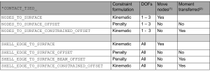
For tied contacts involving structural elements (nodes having 6 Degrees of Freedom) the SHELL_EDGE_TO_SURFACE – options
are recommended.
Tied contacts may be defined using parts or part sets, but for maximum control over which nodes that get tied, a node set
can be used as the tracked (SURFA) side (SURFATYP=4).
For tied contacts using kinematic constraints, the option to automatically create a penalty fallback tied contact for nodes
that fail to get tied due to conflicting constraints (by setting IPBAK = 1 on Optional Card D) is recommended.