A disk is attached slightly off-center to a rotating shaft (omega = 200). The shaft is attached to a rigid fixture, see Figure 33. The fixture in turn is spinning around the X-axle. The rotational axis of the shaft is defined using *DEFINE_VECTOR_NODES and two nodes in the rotating fixture. A rotating coordinate system is applied for the rotational dynamics analysis.
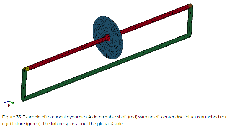
The keyword file for this example is run_rotodyn.key. The analysis is performed using non-linear transient dynamics (compare Section 4.8) and the control cards of control_cards_nolin.key. To
account for the rotational motion, the composite Bathe time integration scheme is used (ALPHA = 0.5 on *CONTROL_IMPLICIT_DYNAMICS), compare Section 4.8.
Example Files: run_rotodyn
NOTE! All examples are included in the Complete Guideline
*KEYWORD
$===============================================================================
$ Control cards
$===============================================================================
*INCLUDE
../INCLUDE_FILES/control_cards_nonlin.key
*INCLUDE
../INCLUDE_FILES/database_cards_static.key
*CONTROL_IMPLICIT_GENERAL
$#  imflag       dt0    imform      nsbs       igs     cnstn      form    zero_v
         1  1.000e-3         2         1
*CONTROL_IMPLICIT_DYNAMICS
$#   imass     gamma      beta    tdybir    tdydth    tdybur     irate
         1                                                           1       0.5
*CONTROL_IMPLICIT_AUTO
$    IAUTO    ITEOPT    ITEWIN     DTMIN     DTMAX     DTEXP
         1       100        20     1.E-6     -700.        0.
*CONTROL_IMPLICIT_SOLUTION
$#  nsolvr    ilimit    maxref     dctol     ectol     rctol     lstol    abstol
        12         1        65     1.E-3     1.E-2                        1.E-20
$#   dnorm    diverg     istif   nlprint    nlnorm   d3itctl
         1         1         1         3         2         1
$#  arcctl    arcdir    arclen    arcmth    arcdmp

$#   lsmtd
         5
*DEFINE_CURVE_TITLE
Implicit timesteps
700,
0.,1.E-4
1.,1.E-3
*CONTROL_TERMINATION
$#  endtim    endcyc     dtmin    endeng    endmas
  0.100000         0     1.E-6
*CONTROL_MPP_IO_NODUMP
$===============================================================================
$ Database cards
$===============================================================================
*DATABASE_BINARY_D3PLOT
$#      dt      lcdt      beam     npltc    psetid
  1.000e-3         0         0         0         0
*SET_NODE_LIST_TITLE
output nodes
$#     sid       da1       da2       da3       da4    solver
         1
$#    nid1      nid2      nid3      nid4      nid5      nid6      nid7      nid8
         1        51
*DATABASE_HISTORY_NODE_SET
         1
$===============================================================================
$ Loads and boundary conditions
$===============================================================================
*CONTROL_IMPLICIT_ROTATIONAL_DYNAMICS
$---+----1----+----2----+----3----+----4----+----5----+----6----+----7----+----8
$#     sid     itype     omega       vid    nomega    irefer
         1         1    200.00         1         0         2
*DEFINE_VECTOR_NODES
         1         1        51
*SET_PART_LIST_TITLE
Rotating parts
$#     sid       da1       da2       da3       da4    solver
         1
$#    pid1      pid2      pid3      pid4      pid5      pid6      pid7      pid8
         1         2
*BOUNDARY_PRESCRIBED_MOTION_RIGID
         3         5         2       110
*DEFINE_CURVE_TITLE
Rotational displacement 1 rad in 0.1 s
       110
0.,0.
0.1,1.
1.,1.
$===============================================================================
$ Geometry
$===============================================================================
*INCLUDE
geo_rotodyn.key
$===============================================================================
$ Simulation title
$===============================================================================
*TITLE
Rotational dynamics example - nonlinear transient implict dynamic
*END