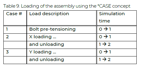
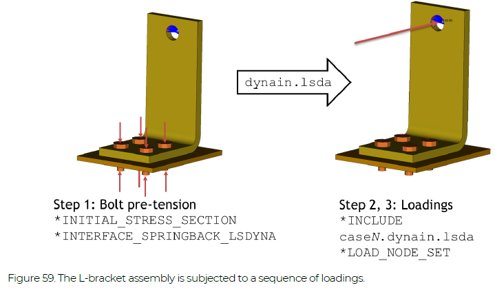
An L-shaped bracket assembly is subjected initially to bolt pre-tensioning followed by loadings in the X and Y directions, see Figure 59. The analysis of these load stages is set up as a sequence of three cases, as described in Table 9.
Example Files: DYNAIN
NOTE! All examples are included in the Complete Guideline
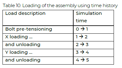
The information is propagated between the analyses using the dynain.lsda binary format files. The main run file is L_bracket_dynain.key. For reference, also an all-in-one analysis is set-up (L_bracket_allin1.key), where the loadings vary with simulation time according to Table 10.
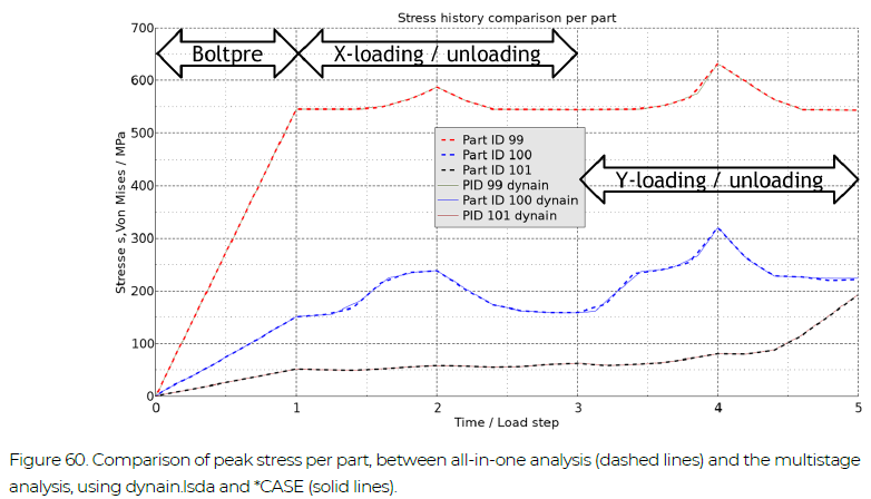
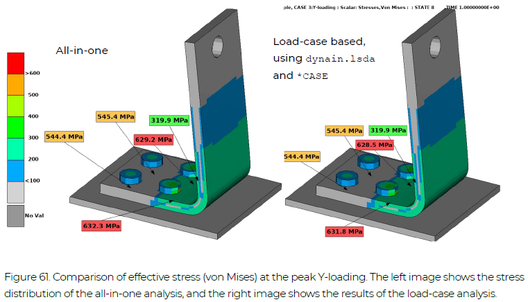
The history of peak effective stress in each part for the two analysis approaches are compared in Figure 60, where the results from the multistage approach have been time-shifted to match the all-in-one analysis. The general agreement is very good, indicating the capability of the dynain.lsda file to carry the state information forward between analyses. In Figure 61, fringe plots of the effective stress at the peak Y-loading are compared between the two analysis approaches. Only very small differences (0.1 %) can be noted.
*KEYWORD
$===============================================================================
$ Geometry
$===============================================================================
*INCLUDE
bolts_partsec.key
$===============================================================================
$ Control and output cards
$===============================================================================
*INCLUDE
../../INCLUDE_FILES/control_cards_nonlin.key
*INCLUDE
../../INCLUDE_FILES/database_cards_static.key
*DEFINE_CURVE_TITLE
Time stepping curve
       700
                  0.                0.05
                  1.                 0.2
                  2.                 0.2
                  3.                 0.2
                  4.                 0.2
                  5.                 0.2
*CONTROL_MPP_IO_NODUMP
$===============================================================================
$ Contacts
$===============================================================================
*CONTACT_AUTOMATIC_SINGLE_SURFACE_MORTAR_ID
1010      Bolts all contact
       111                   2
      0.15
        5.


         5
$===============================================================================
$ Loading and boundary conditions
$===============================================================================
*BOUNDARY_SPC_SET
       112                   1         1         1
$===============================================================================
$ Additional output
$===============================================================================
*DATABASE_HISTORY_NODE_SET
       109
*CONTACT_FORCE_TRANSDUCER_PENALTY_ID
  19000004Bolts to plate
         4       101         2         3


$===============================================================================
$ Cases
$===============================================================================
*CASE_BEGIN_1
*INCLUDE
bolts_nodel.key
*INCLUDE
run_pretens.key
*CASE_END_1
*CASE_BEGIN_2
*INCLUDE
case1.dynain.lsda
*INCLUDE
run_xload.key
*CASE_END_2
*CASE_BEGIN_3
*INCLUDE
case2.dynain.lsda
*INCLUDE
run_yload.key
*CASE_END_3
*END