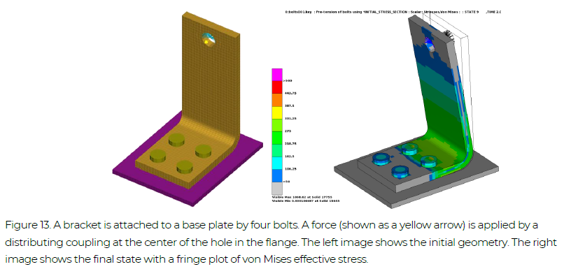
A bracket is connected to a base plate by four bolts, see Figure 13. Bolt pre-tensioning is performed between t = 0 and t = 1. The LS-DYNA keyword *INITIAL_STRESS_SECTION is used to apply the bolt pretensioning. From t = 1 to t = 2, a load is applied at the free hole of the flange via a distributing coupling (*CONSTRAINED_INTERPOLATION). The example keyword file is bolts001.key.
Example Files: bolts001
NOTE! All examples are included in the Complete Guideline
Implicit dynamics is used during the bolt pre-tensioning in order to overcome the fact that the model initially contains rigid-body modes. A template for using implicit dynamics for this purpose follows:
*KEYWORD
*INCLUDE
control_cards_nonlin.key
*DEFINE_CURVE_TITLE
Implicit time incrementation
700,
0., dt0 (first timestep)
Additional lines to define time incrementation
*CONTROL_IMPLICIT_DYNAMICS
1, GAMMA, BETA, 0., TDYDTH, TDYBUR, IRATE
*INCLUDE
database_cards_static.key
*CONTROL_TERMINATION
Define end time of the simulation
*INCLUDE
Include file defining geometry, materials etc.
*LOAD_...
Define nodal loads etc.
*BOUNDARY_...
Data line to prescribe boundary conditions
*TITLE
Simulation title
*END
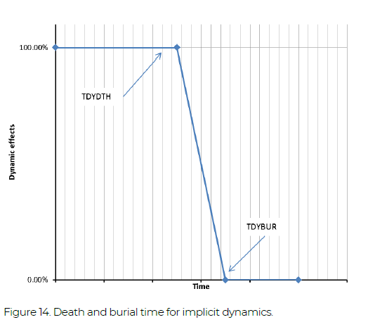
The parameters GAMMA and BETA of the *CONTROL_IMPLICIT_DYNAMICS keyword (see also Section 4.8) control the time integration. Normally GAMMA = 0.6 and BETA = 0.38 are used in order to introduce some numerical damping, when the purpose is to use implicit dynamics in a (quasi) static analysis to resolve initial rigid-body modes. The parameter TDYDTH is the time when the dynamic effects start to ramp off, and at time TDYBUR the dynamic effects are completely removed, see Figure 14. Setting the parameter IRATE = 1 will switch off the rate effects in material models, see further Section 7.
*KEYWORD
$===============================================================================
$ Geometry
$===============================================================================
*INCLUDE
bolts_geo.key
$===============================================================================
$ Control and output cards
$===============================================================================
*INCLUDE
../INCLUDE_FILES/control_cards_nonlin.key
*INCLUDE
../INCLUDE_FILES/database_cards_static.key
*CONTROL_TERMINATION
$   ENDTIM    ENDCYC     DTMIN    ENDENG    ENDMAS
        4.
*CONTROL_IMPLICIT_DYNAMICS
$    IMASS     GAMMA      BETA                                   IRATE
         1       0.6      0.38       0.0       0.5      0.70         1
*DEFINE_CURVE_TITLE
Time stepping curve
       700
                  0.                0.05
                  1.                 0.2
                  2.                 0.2
                  3.                 0.2
                  4.                 0.2
                  5.                 0.2
*CONTROL_MPP_IO_NODUMP
$===============================================================================
$ Contacts
$===============================================================================
*CONTACT_AUTOMATIC_SINGLE_SURFACE_MORTAR_ID
1010      Bolts all contact
       111                   2
      0.15
        5.


         5
$===============================================================================
$ Loading and boundary conditions
$===============================================================================
*BOUNDARY_SPC_SET
       112                   1         1         1
$ --- Bolts pre-tensioning
*INITIAL_STRESS_SECTION
         1         1      1002         4
         2         2      1002         4
         3         3      1002         4
         4         4      1002         4
*DEFINE_CURVE_TITLE
Bolt pre-tension 448 MPa
      1002                          448.
0.,0.
1.,1.
$ --- Loading
*LOAD_NODE_SET
$     nsid       dof      lcid        sf
       109         1      1001      1.E3
       109         2      2001      1.E3
*DEFINE_CURVE_TITLE
Loading X
      1001
0.,0.
1.,0.
2.,1.
3.,0.
*DEFINE_CURVE_TITLE
Loading Y
      2001
0.,0.
1.,0.
2.,0.
3.,1.
4.,0.
$===============================================================================
$ Additional output - elout
$===============================================================================
*DATABASE_HISTORY_NODE_SET
       109
*CONTACT_FORCE_TRANSDUCER_PENALTY_ID
  19000004Bolts to plate
         4       101         2         3


$===============================================================================
$ Simulation title
$===============================================================================
*TITLE
Bolts pre-tensioning example
*END